Automating my Kitchen Rangehood Fan and Light

I originally posted this write-up on the Home Assistant Community Forums. I thought I would post it here as well, since I haven't written anything on this blog for a while. I've been getting more serious about Home Automation lately, so I might start writing some more blog posts and making a few videos.
I figured out how to control the light and fan in the rangehood above my stove. I learned a lot from this project, and I wanted to share some of my experiences.
- I figured out how to read the state of 4 buttons and light up 4 LEDs with only 5 wires
- I discovered some powerful circuit simulation software
- I used optocouplers for the first time (instead of relays)
- I wrote some C++ code for a custom ESPHome component
- I bought an oscilloscope
Introduction
I wanted to be able to control the light and extractor fan above my stovetop, so I decided to automate it using an ESP32. This would be a similar concept to the Raspberry Pi Microwave project that I built many years ago: I would put a "proxy" circuit between the buttons and the main board that controls the light and fan. The circuit would simulate button presses to control the main board, and it would read the state of the original buttons so that they would still work normally. The circuit would add WiFi connectivity so that the buttons could be controlled remotely and via automations in Home Assistant.
I still use Raspberry Pis, but now I prefer using ESP32 and ESP8266 chips. ESPHome makes it so much easier to build little devices like this, and the OTA (over-the-air) updates are really convenient. I love all the built-in components that you can easily add to your YAML configuration files.
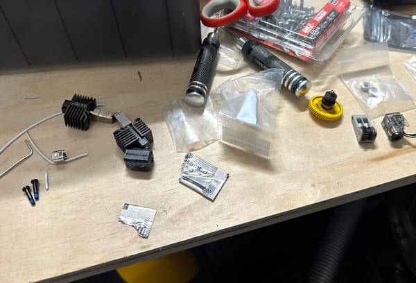
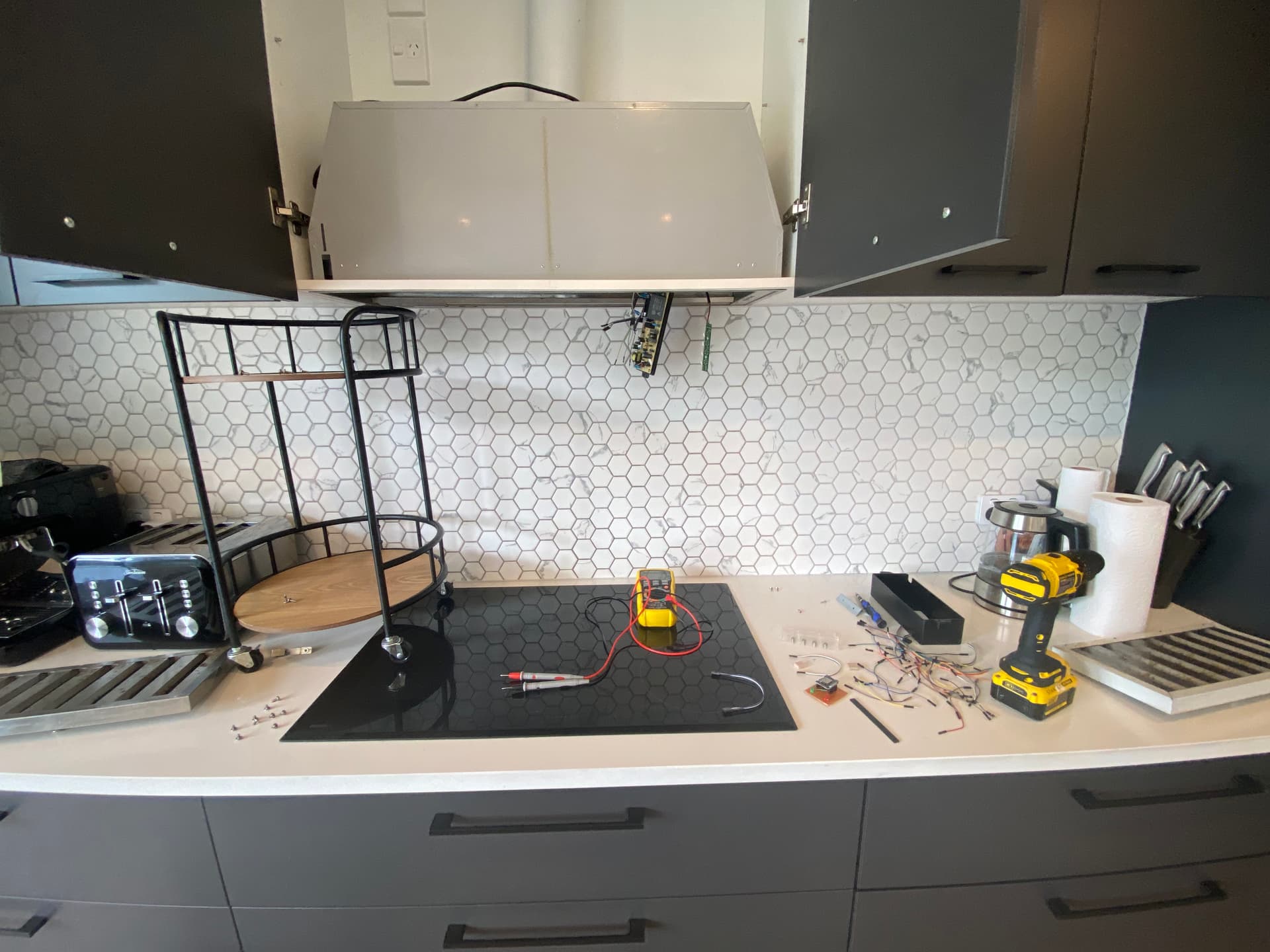
Here's a photo of the rangehood, with some of my tools. You can see the main controller board and the button board hanging out.
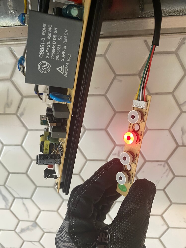
This is the button board, which has 4 buttons, and an LED for each button:
How to read 4 buttons and light 4 LEDs with only 5 wires
I wanted to preserve the original functionality of the rangehood buttons, so that you wouldn't even know there's an ESP32 chip inside. This button board was the first obstacle. If there were only 4 buttons, then that would be quite easy. You can just attach them directly to GPIO pins with an internal pull-up resistor. The LEDs were a bit confusing at first, but it was a fun puzzle to solve.
I took a photo of the PCB and traced it using different colors, so I could where each of the wires was going:
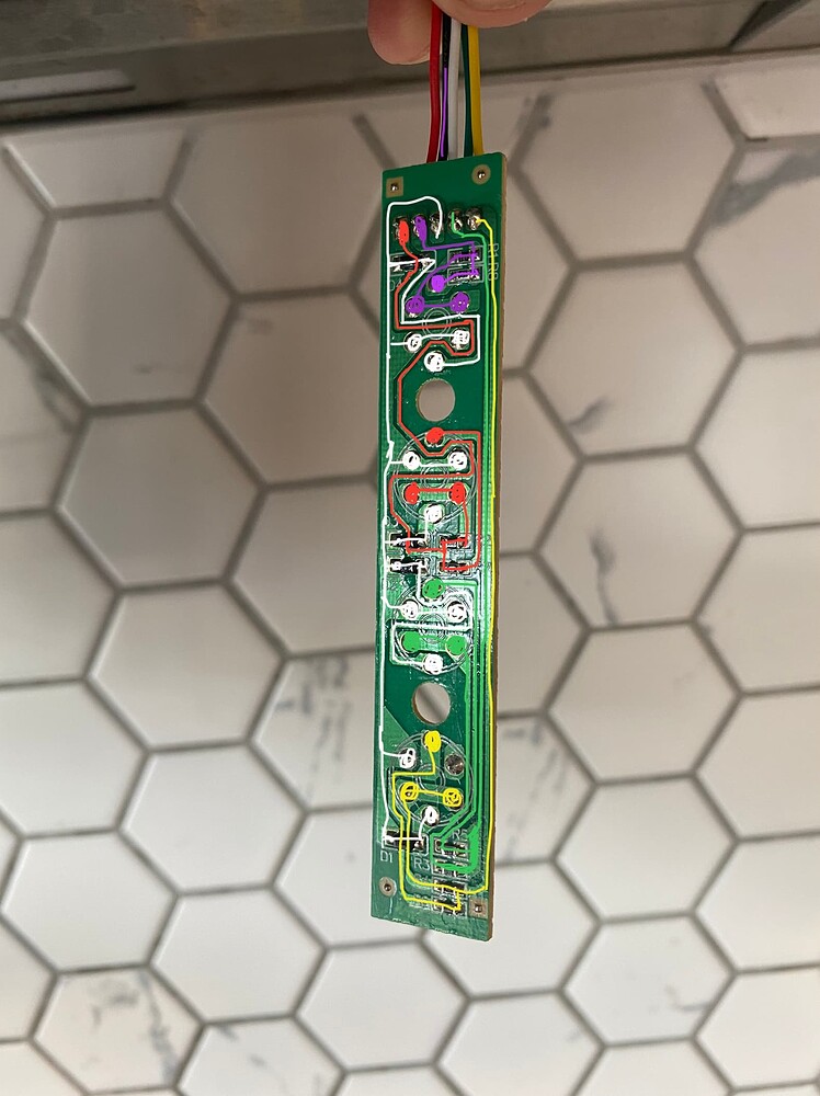
I found that button has a 1K ohm resistor, and each LED has a 148 ohm resistor.
Circuit simulation software
I'm a software developer, so I really like having fast feedback loops and the ability to try lots of ideas quickly to see if something works. I started wondering if it might be possible to do this with circuits. I wanted to see if I could figure this out with trial and error and use some kind of circuit simulation software.
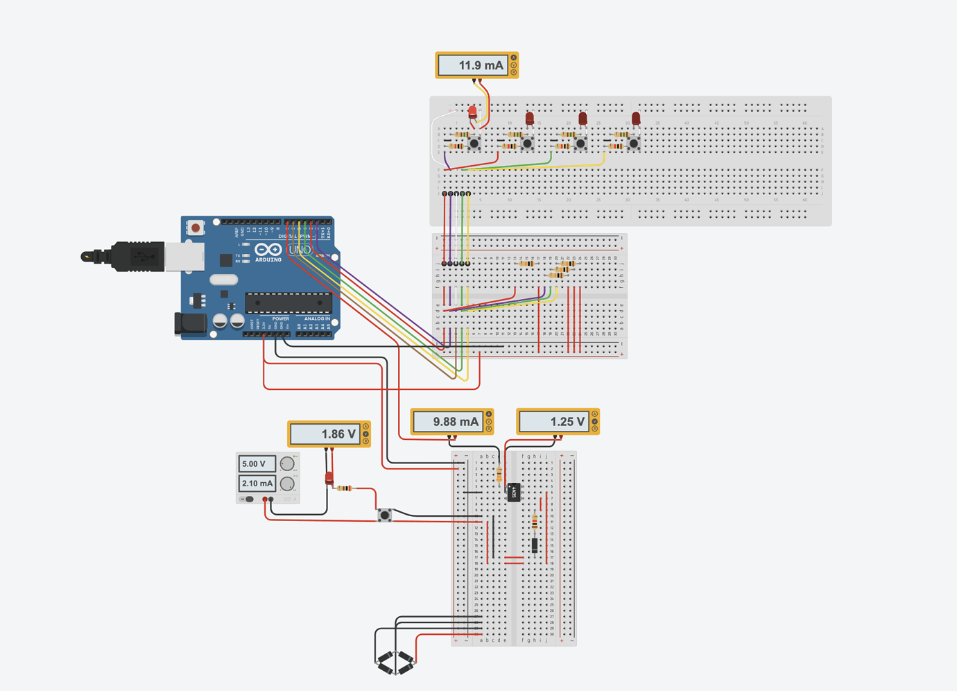
I found TinkerCad, and my mind was blown! Now I had a virtual Arduino wired up to a virtual breadboard. I recreated this button/LED board inside TinkerCad. I could set up virtual multi-meters to see how much current was flowing through LEDs, and easily figure out values for resistors.
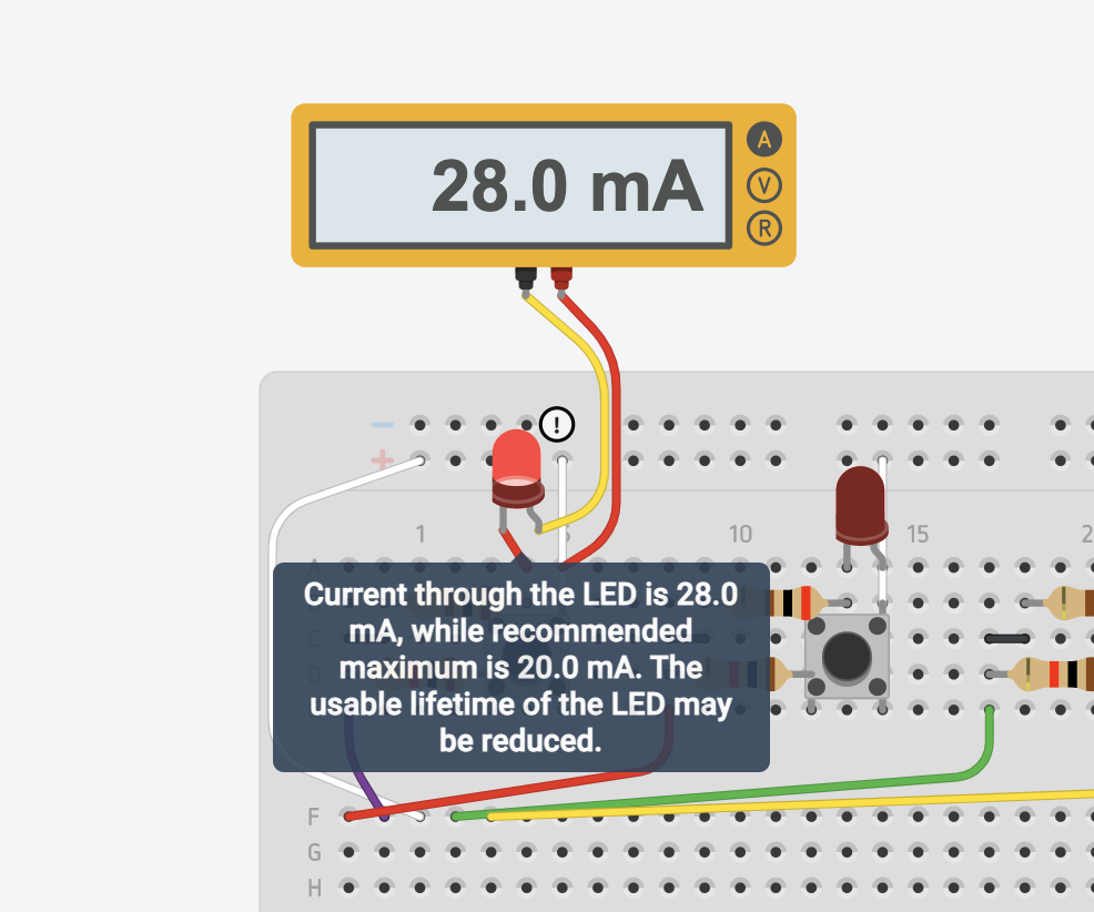
This is so awesome! It even tells you when too much current is going through an LED:
Here's a link to my TinkerCad project where you can run the circuit simulation.
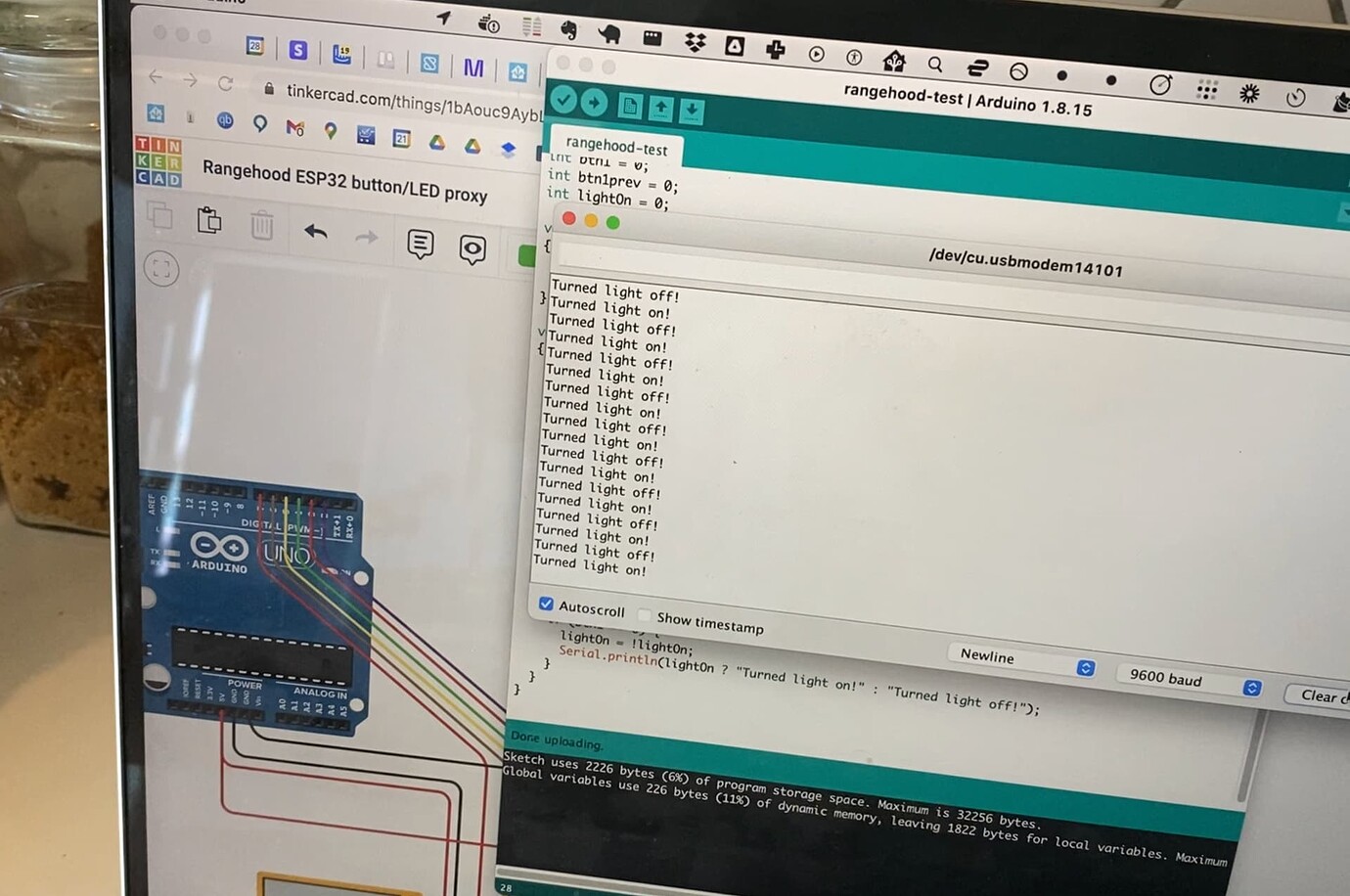
I started playing around with some code in an Arduino sketch. I figured out how to light up the LEDs. I figured out how to read the buttons. But I couldn't figure out how to do them both at the same time. If I wanted to light up the LEDs, then I'd need to be using 3.3V on the shared wire. But if I wanted to read the buttons, then the shared wire needed to be connected to GND.
Then I finally had a breakthrough. Whenever I had worked with GPIO pins in the past, I had just assumed that "high" and "low" meant "on" and "off". But I realized that "high" literally just means 5V (or 3.3V), and "low" literally just means GND. So you can just change the direction of a circuit if you set your output pins to normally "high", and you swap the GND pin with a 3.3V pin.
So instead of needing to choose between the 3.3V pin and the GND pin, I could use a GPIO pin on the shared wire and toggle it between "high" and "low". I set it to "low" whenever I needed to read the buttons, and set it to "high" whenever I needed to light up the LEDs.
I got something working in my virtual Arduino. The other side of the circuit was quite easy (to simulate the button presses.) I used some optocouplers as relays, where you send current through an IR LED and it turns on a transistor on the other side, but it keeps both of the circuits separated. Later on I realized that I should have been looking at "solid state relays", which are optocouplers that are specifically designed for this purpose and can switch much higher voltages and currents.
I tried it out with a real Arduino, and it worked!
It was a pretty cool experience to simulate a whole Arduino circuit inside my browser, and then see it work in real life.
https://everycircuit.com is also a really cool option for circuit simulation:
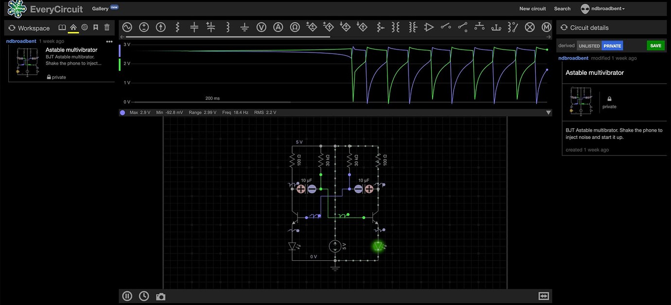
It can handle some things that TinkerCad can't do, such as astable multivibrator circuits where you need to inject a little noise to get it started. (TinkerCad just crashes with an "infinite loop" error.)
Custom C++ ESPHome Component
Alright, on to the next step. I've got something working with an Arduino, but how do I port this to ESPHome and get it working over WiFI?
I needed to set an GPIO pin to output mode for a while, briefly switch it to input mode, read the state of a button, and then set it back to output mode again. I couldn't figure out how to do this in a YAML configuration file for ESPHome, so I decided to write a custom component using C++.
The ESPHome documentation is pretty good, and I was able to get something working. Here's my YAML configuration and my custom C++ module: https://gist.github.com/ndbroadbent/63aa5f105e21631bee4ff9a62c9b1608
The most important difference between Arduino and ESPHome is that a component's loop() function is only called once every 16 milliseconds. (Arduino restarts the loop instantly.) This was actually perfect for me, since it meant that I could read the buttons once every 16ms, and leave the LEDs on before I exit the loop.
I ran out of pins on my ESP8266 (Wemos D1 Mini)
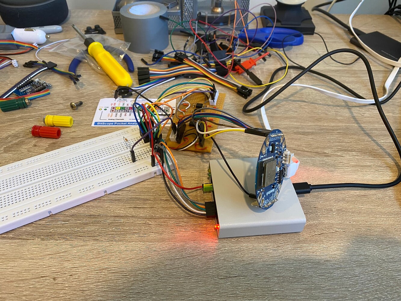
I should have made sure that everything worked on a breadboard. Instead, I started to get a bit impatient, and I jumped straight to soldering a prototype PCB. I soldering some pin headers for my ESP8266 development board, and then started with one input, and one optocoupler for the output. I tested it and it was all working, so I kept going.
Then I checked the ESP8266 pinout and realized that I had run out of GPIO pins.
I tried to get away with using some of the yellow "OK" ones, but the boot started failing (I guess I was pulling some of the pins high or low.) I needed 4 pins to control the optocoupler outputs, and 5 for the button/LED board. That's 9 GPIO pins, and the ESP8266 only had 7. I thought it had more!
This can be solved with shift registers. You only need 3 GPIO pins to control a 74HC595 8-bit shift register and get 8 digital outputs. You only need one additional GPIO pin if you want to add a CD4021BE shift register (parallel-in, serial-out) and get 8 digital inputs. This is because the input and output registers can share the same clock and latch pins. You can then daisy-chain both of these to get as many inputs and outputs as you need (or use bigger shift registers with more pins), and use only 4 GPIO pins.
Anyway, I switched to using an ESP32 development board which has 18 usable GPIO pins, and a few more with caveats. I used breadboard jumper wires to wire it up.
My resistors were too big
I had put 1k resistors on the optocoupler outputs, to mimic the original button/LED board. What I didn't realize is that the optocoupler itself seemed to add about 500 ohms of resistance, so the resistance was slightly too high, and the rangehood controller board couldn't reliably read the simulated button presses.
So I unsoldered them and switched to 560 ohm resistors. Should have tested on a breadboard.
I bought a USB oscilloscope
After doing a bunch of unsoldering and resoldering, putting random hookup wires all over the place, and swapping out ESP dev boards, I ended up with the ugliest prototype PCB you've ever seen. Of couse, stuff started breaking and one of my outputs wasn't working properly or reliably. It seemed like there was a problem with one of my optocouplers, and it was a real pain to figure out what was broken since I had only had a multimeter.
I realized that a oscilloscope would be really useful, and I should have bought one a long time ago. I bought a USB BitScope 10. It's pretty cool!
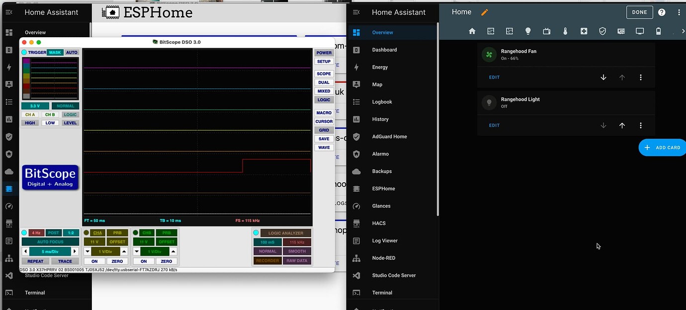
This helped me figure out where some things needed to be resoldered. One of the optocouplers was only working when I pushed on it with my finger. I originally thought it might have been a broken chip or something to do with capacitance, but it was just a broken PCB trace and some dodgy soldering.
I'm still learning how to use the BitScope software and have barely scratched the surface of what it can do. This is going to be extremely useful for future projects, especially for reverse engineering how stuff works. (P.S. You'll need their pre-release version for the latest version of Mac OS.)
WiFi was very weak on my "Duinotech Wearable ESP32 Development Board"
I initially switched to a Duinotech Wearable ESP32 Development Board that I had bought a while ago. I got everything working, but then it really struggled to connect to WiFi and would cut out regularly, and my entities would become unavailable. Even though I had a Ubiquity access point only 10 meters away in the same room.
I found a few other people who seemed to have problems with WiFi as well, but they might be for different reasons:
- https://www.esp32.com/viewtopic.php?t=16311
- https://forum.micropython.org/viewtopic.php?t=11550&p=63020
- https://www.esp32.com/viewtopic.php?t=18159
- https://www.esp32.com/viewtopic.php?t=16622
- https://www.esp32.com/viewtopic.php?t=6073
- https://www.reddit.com/r/esp32/comments/bbjrir/very_poor_wifi_performance/
Then I found the "WiFi Power Save Mode" section in the ESPHome documentation:
NONE(least power saving, Default for ESP8266)LIGHT(Default for ESP32)
So I tried:
wifi:
  power_save_mode: none
  output_power: 20
I think this seemed to help a little bit, but it still wasn't very reliable. I had ordered some more electronics stuff and threw in another ESP32 Development Board. I tried this out once it arrived and it was an instant improvement. I just threw away the board with poor WiFi. I also ordered a bunch of shift registers so I can get back to using ESP8266 boards (adafruit huzzuh feathers), and they seem to have much better WiFi as well.
I also ordered a few extra Wemos D1 Mini Pros that support external antennas. They haven't arrived yet, but I might try these out for car presence detection. I've been struggling with WiFi range for this as well.
Putting it all together
I put everything into a little black box. Connected all the wires up and stuck it inside the rangehood. I chopped the power cable for the rangehood and added a screw terminal, and wired up a USB charger to power the ESP32 board.
So now I've got the fan and light in Home Assistant. (And the physical buttons still work as well.)
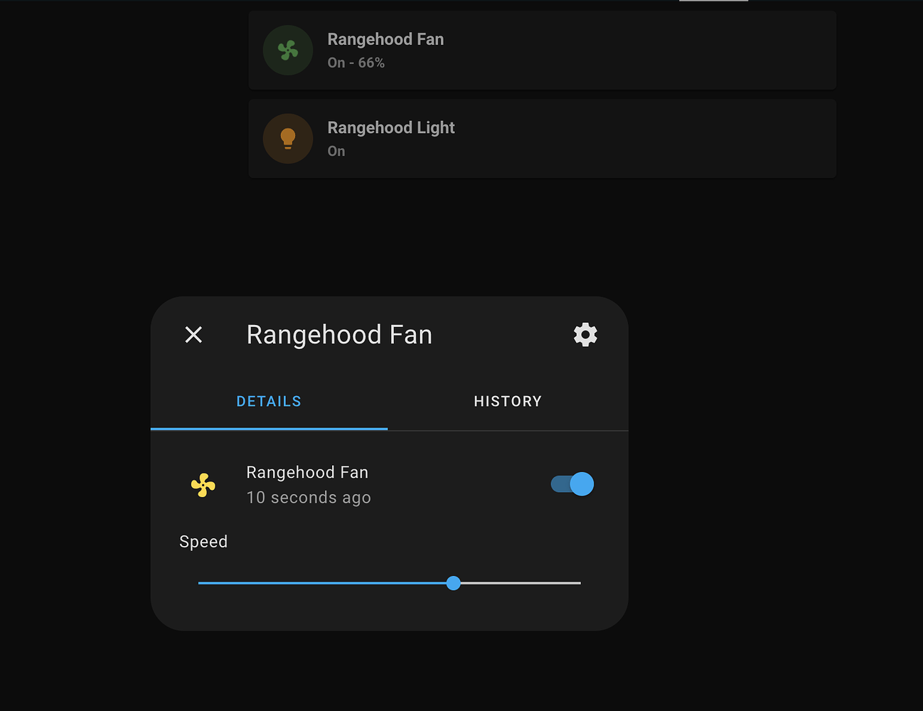
I've set up an entity controller to turn on the light.
Next steps
The rangehood controller board has a piezo buzzer that beeps every time a button is pressed. That's pretty annoying. I might try to desolder or destroy the buzzer.
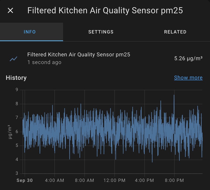
I want to put an air quality sensor in the kitchen and automatically turn on the extractor fan based on AQI. I've ordered some ZigBee air quality meters on AliExpress, and they should arrive in a few weeks.
Update from Sep 30, 2022: I've put the air quality sensor in the kitchen, and have set it up to turn on the rangehood fan when the PM 2.5 level is above 12 µg/m³. (It usually hovers around 6 µg/m³.) It's been working really well!
I also bought a current clamp sensor that can measure AC current. I want to set this up for the stovetop so I can detect when it's on and automatically turn on the fan (in advance, instead of waiting for the AQI to get bad.) It would be easier if I could use an energy monitoring wall plug, but it looks like the stovetop is wired directly into the circuit breaker, and it uses a lot of power so I don't want to mess around with those wires. I'll just separate them and put a clamp around one of them. I'll follow this guide to set it all up and get it working on an ESP32.
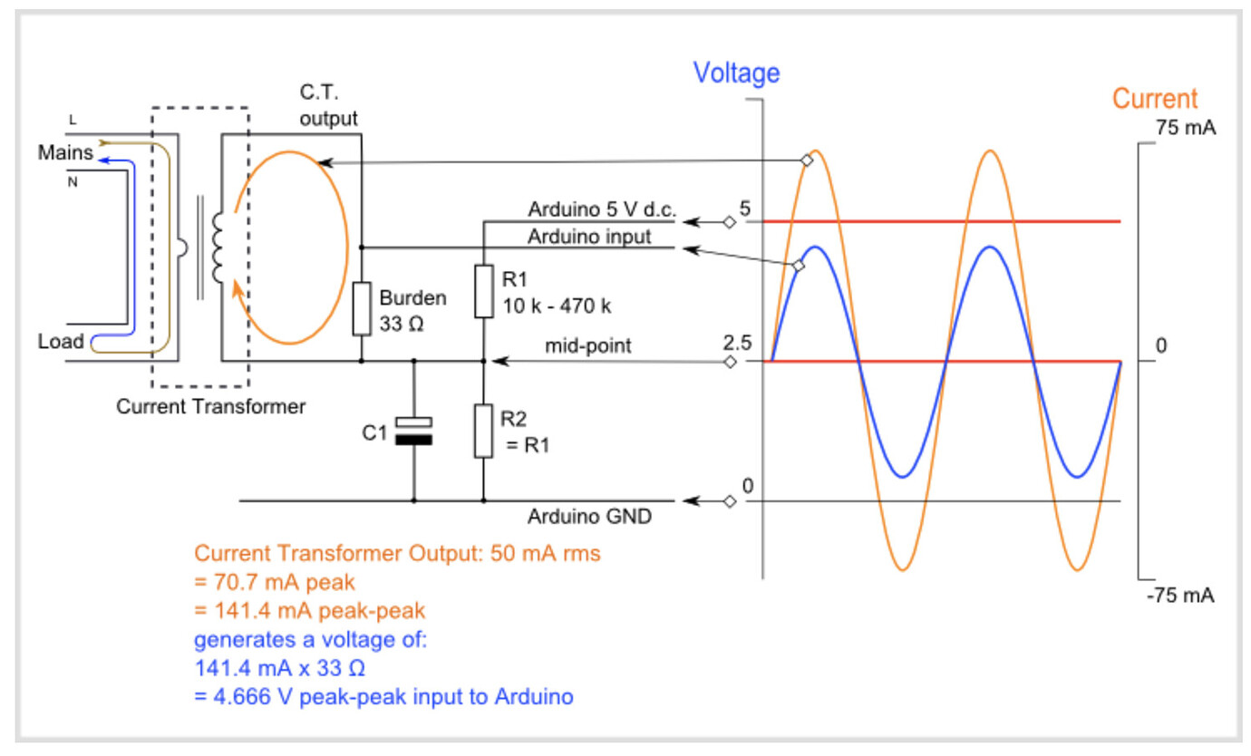
I have this power meter that I'll use to calibrate it.
I also want to learn how to make a proper PCB design in KiCad and order a cool purple PCB from OSH park.
I'm really enjoying this self-directed crash course in electronics. It's really fun to learn so much while working on practical projects that we can use every day in our house.
Thanks for reading, it was fun to write up everything I learned. If you have any questions, please feel free to ask in the comments!